Changsha BSL Info. Tech. CO.,Ltd.
Honesty is the foundation, Dare to innovate
Column
8613913227693


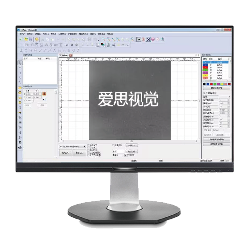
Eyes: Visual Marking Control System
Installed on the marking equipment and used in conjunction with the BSL marking control system, it can achieve the laser processing operation of "point and shoot" and "what you see is what you get".
Technical Parameters:
EYES visually for the standard paraxial mounting, in which the camera / lens / light source throughthe adiustment mechanism mounted on top of the field mirror, the light source is used to fill thelight and can be removed, the camera mounting angle can be adjusted, the system can be up to the technical indicators are as follows: | |
| Camera Resolution (Max) | 1920*1080 |
| Camera Lens Mounting Height | 250mm-300mm |
| Camera Lens Mount | Support mounting at 0/90/180/270 degree angles to the galvanometer coordinates. |
| Camera Effective Shooting Range | ≥180mm*180mm |
| Calibration Range of Calibration Plate | 160*160mm(40*40*4*0.1mm) |
| Max Format of Laser Marking | 180mm*180mm and below |
| Single Pixel Accuracy | ≤0.1mm |
| Visual Marking Overlap Accuracy | ±0.1mm |
| Maximum Deformation of Marking Pattern | 0.3% |
Description of Definitions:
| Visual Marking Coincidence Accuracy : |
| In the galvanometer coordinate system to specify any position for patternmarking, the pattern captured by the visual system for mapping alignment, and the maximum deviation from thetheoretical position of the marking file. Usually mark a rectangle within the maximum marking range, observethe center of the galvanometer coordinate system and the four corners of the alignment, the maximum devia.tion of the sizeis not higher than ± 0.1mm. |
| Maximum Deformation of the Marking Pattern : |
| The proportion of deviation between the size of the drawn patternand the actual size of the marking, when the pattern is marked at an arbitrary position within the galvanometercoordinate system. |